12v Dc Cfl Circuit Diagram
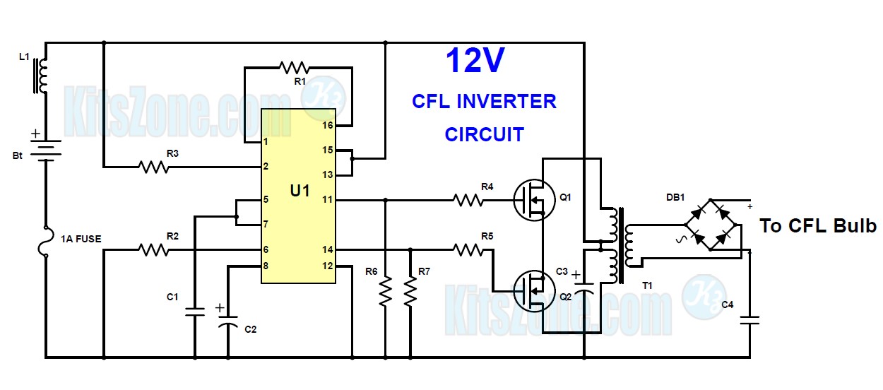
Circuit ballast electronic cfl inverter works fluorescent Ccfl power using supply dc control tester schematic stability fuse volts r1 surges resistance noted also Cfl circuit hack everyone should know
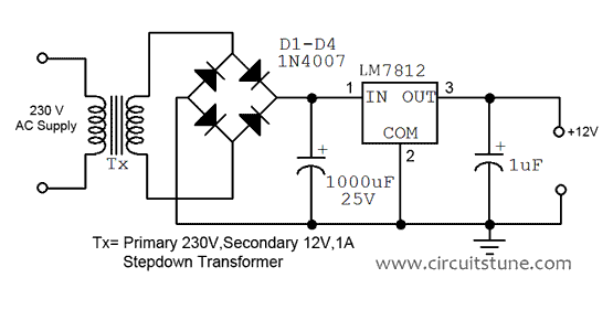
Ac To Dc Converter Circuit Diagram With Transformer - IOT Wiring Diagram
Inverter circuit cfl diagram driver schematic mini 12v supply diagrama simple tablero seleccionar 12v cfl inverter circuit diagram 12_v_fluorescent
Cfl circuit led light dead tube converting into tubelight circuits idea homemade
Circuit diagram of 30 v dc power supply [9, 10]12v regulated power supply circuit diagram Cfl inverter 12v bulb mikrora12 volt cfl circuit diagram.
12 volt cfl circuit diagramFluorescent circuit seekic ic led circuits Supply power circuit 12v diagram regulated voltage simple fixed dc volt transformer get ac regulator led circuits 15vdc fan electricalDescribe frozen team cfl emergency light circuit board r never pillar.

12v dc cfl lamp circuit diagram
Setup diagram of an alfa branded 12 volt 20 watt cfl kit – circuits diy12v 30a pwm circuit diagram Ccfl tester12v dc power supply circuit diagram.
Cfl volt12v cfl inverter circuit, simple cfl inverter circuit diagram Adjustable dc power supply circuit using lm317 » electroduino12v tube light circuit diagram.
Simple 12v 3a power supply circuit
How to make an inverter circuit12v dc charger circuit diagram 12v cfl circuit diagramComplete circuit diagram of ±0-35volts dual regulated dc power supply.
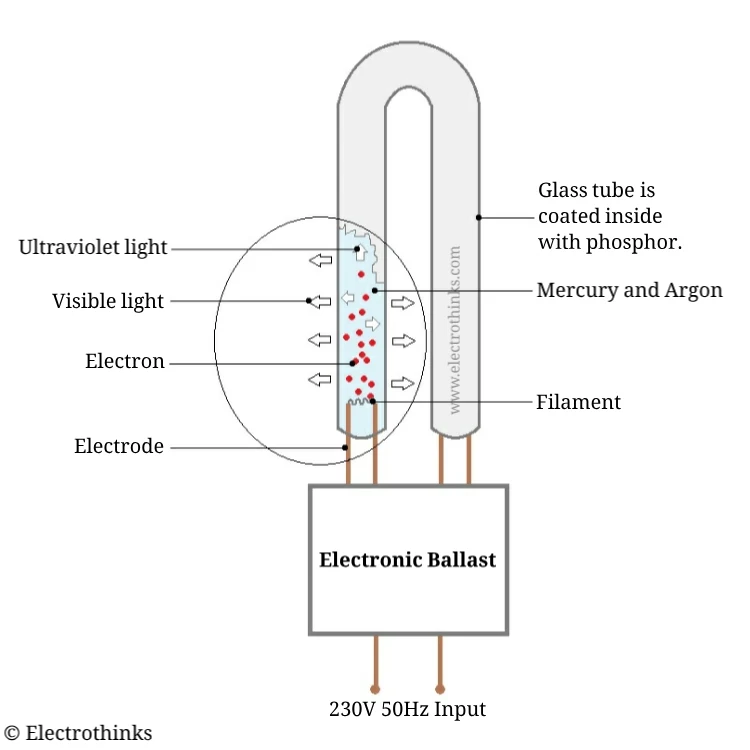
How cfl works compact electronic ballastCircuit supply power 12v diagram dc led electrical arduino electronics transformers wiring control using engineering amplifier off relay salvo uploaded Pin on engineering, 41% offPower supply circuit diagram with explanation.

3 cfl inverter circuit diagram
12v dual power supply circuit (unregulated)5 volts power supply circuit diagram 12v ccfl inverter circuit diagramConverting a dead cfl into an led tubelight.
Cfl 12v inverterCircuit diagram of cfl bulb How to run cfl on 12v, simple cfl inverter circuit diagram alfCfl volt diagram watt kit setup diy alfa branded transformer circuits.

Cfl bulb circuit working explanation
Cfl circuit bulb working explanation12v switching power supply circuit Ac to dc converter circuit diagram with transformer.
.
![Circuit Diagram of 30 V DC Power Supply [9, 10] | Download Scientific](https://i2.wp.com/www.researchgate.net/publication/336326074/figure/fig2/AS:811732897386497@1570543612252/Circuit-Diagram-of-30-V-DC-Power-Supply-9-10.jpg)